Measurement with PAK live
This guide shows how to setup a measurement with PAK 6.3 and the new PAK live Measurement Definition using the example of two PAK MKIIs with an accelerometer, a microphone and CAN data. If you are coming from classical PAK it is recommended to have a look at the changes introduced with PAK live.
Overview, Descriptive Data and Connection of the PAK live Source
The PAK main window provides an own icon button "Measurement (PAK live)" which opens up the following GUI of the PAK live Measurement Definition:
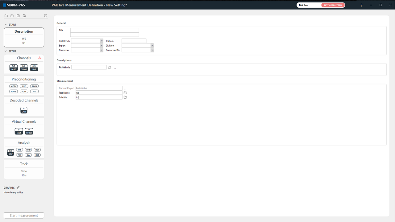
The navigation elements on the left side guide through the workflow. In the left upper corner you have characteristic icons for saving, opening and creating a new PAK live Measurement Definition as well as an gear-shaped icon directing to further options. The first navigation element corresponds to descriptive data and measurement information as you would expect it in a classical measurement definition.
Before continuing with the setup you will need to connect your PAK live source. You can see the connection state of your PAK live source in the top right section, which here says "NOT CONNECTED" highlighted in red. Click on it and a window opens up with available PAK live sources for you to connect. You can choose to filter available sources between PAK live.hubs, PAK MKIIs or others, or you can select to establish a manual connection.
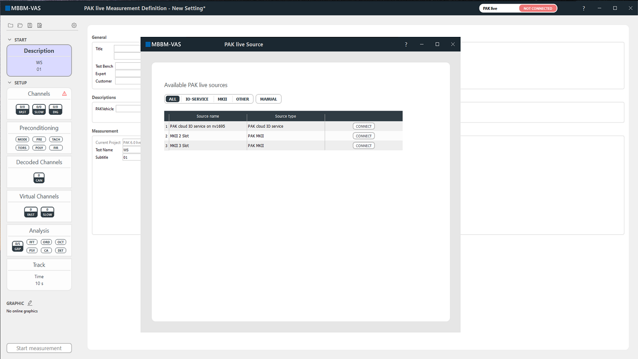
Since we are working here with two PAK MKII devices we connect to a PAK live.hub. As soon as the connection was successfully established, a green highlighted "CONNECTED" indicates this in the title bar of the PAK live Measurement Definition window. In the next step you need to integrate your desired data sources into the PAK live.hub. By selecting the gear-shaped icon you will be redirected to the configuration of the PAK live.hub. As we have added two PAK MKII devices in this example, these are then listed as connected devices of the PAK live.hub, as seen below.
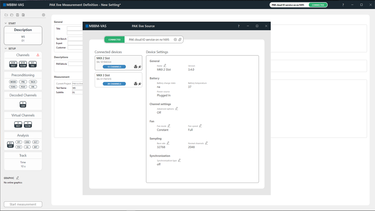
In this window the device settings can be set, individually for each connected PAK MKII device. We change the sampling rate for the 2-Slot PAK MKII to 2048 Hz for the accelerometer and for the 3-Slot PAK MKII to 48000 Hz for the microphone. In this example we do not need synchronized data therefore we turn the synchronization off. Since we do not need to set further device settings we can simply close the PAK live source window in the top right corner. If we want to access the device settings we can do this at anytime during our setup process by clicking on the connection state of our PAK live source in the top right selection of the PAK live measurement definition.
Setting up the PAK live Measurement
We continue the setup by selecting our respective channels which we do by clicking on the "Channels" navigation element on the left. We access all channels from our connected PAK live data sources within this channel table color-coded for each device. The respective channels are sorted as the modules are built within the PAK MKIIs. Besides the interactive segments there are darkened locked entries which show informative data (e.g. device name) or are unreasonable (e.g. direction for a CAN data channel). Note, that you will have to work position-oriented so your position and corresponding quantity needs to be unique. In this table you can change the channel settings which then will be directly applied to your connected devices.
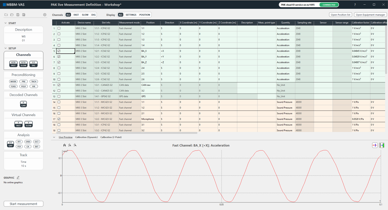
On top of the table you have the possibility to filter the channel display due to all channels, fast channels, slow channels, or digital bus channels. Furthermore, there is the option for showing channel information as well as position information or only channel information or only position information. At the top right, you get access to the Position list and to the Equipment Manager to add positions and sensors with drag-and-drop. Below the table you can open a live preview as well as the possibility to calibrate. Note, that your respective channel needs to be activated and selected to use the live preview. In this example we activated the appropriate channels, entered position and direction as well as the calibration factors and assigned the quantities.
If you adjusted your channel settings you can continue on the left to following navigation element "Preconditioning". Here, you have the possibility to change the measurement mode, apply preprocessing, tacho correction, rotational vibration analysis, polynomial calibration and FIR filtering for the activated and respective channels.

Note, that the settings on the preconditioning tab are calculated and applied within the software, compared to the channels tab where all settings are directly applied to your PAK MKII device. Since we do not need any preconditioning in this example we can skip this part.
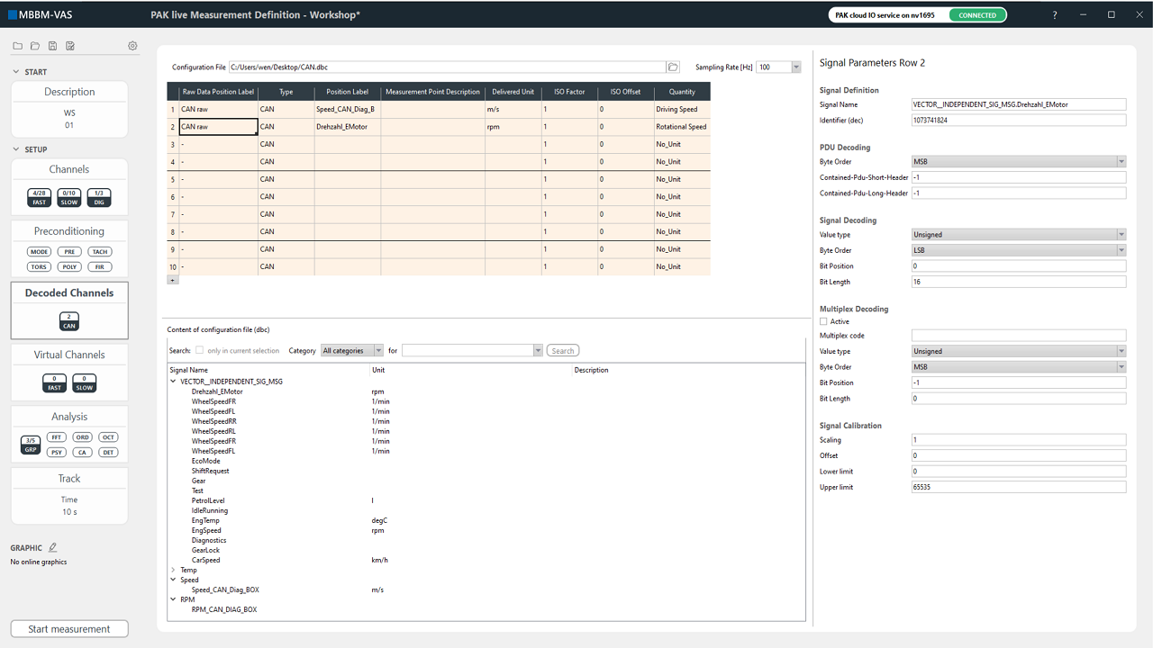
Next up is the "Decoded Channels" navigation element where you can decode CAN signals from your measured CAN raw data within PAK. This part resembles the digital bus configuration which you might recognize from the post-processing or the graphic definition. You first need to select the appropriate configuration file and set your desired sampling rate. Afterwards, in the table at "Raw Data Position Label" you need to select your activated CAN data channel. Your desired decoded signals can be configured by dragging and dropping them from the content of the configuration file at the bottom into the table.
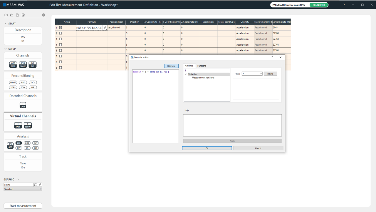
If you want to add a virtual channel which will be computed within PAK you can do this on the next navigation element "Virtual Channels". You need to insert a formula with the well-known formula editor from PAK, a unique position label, as well as quanitiy and sampling rate. Additionally, you can insert further descriptive data. For the sake of clarification we simply added a virtual channel where we multiply the recorded values by two.
For your measured channels you have the possibility to activate online analysis on the navigation element "Analysis". Important to note is that the selected analysis are computed for each respective channel group. This can be seen below:
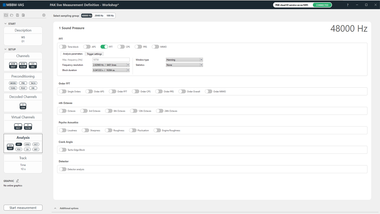
We selected the channel group in which all activated channels with a sampling rate of 48000 Hz are collected. For these channels we applied an FFT by activating the FFT button. All displayed analysis can be applied. The FFT analysis will be only computed for our sound pressure channel connected to the microphone. If you like to apply any kind of analysis to our acceleration signals you first need to switch to the corresponding channel group at the top of the analysis section. Each sampling rate will be put into an own channel group for which the analysis can be applied. At the moment you can only select one sampling group per PAK MKII device. If two or more PAK MKII devices would operate with the same sampling rate, you would have to make sure that these PAK MKII's are synced to assure data acquisition.
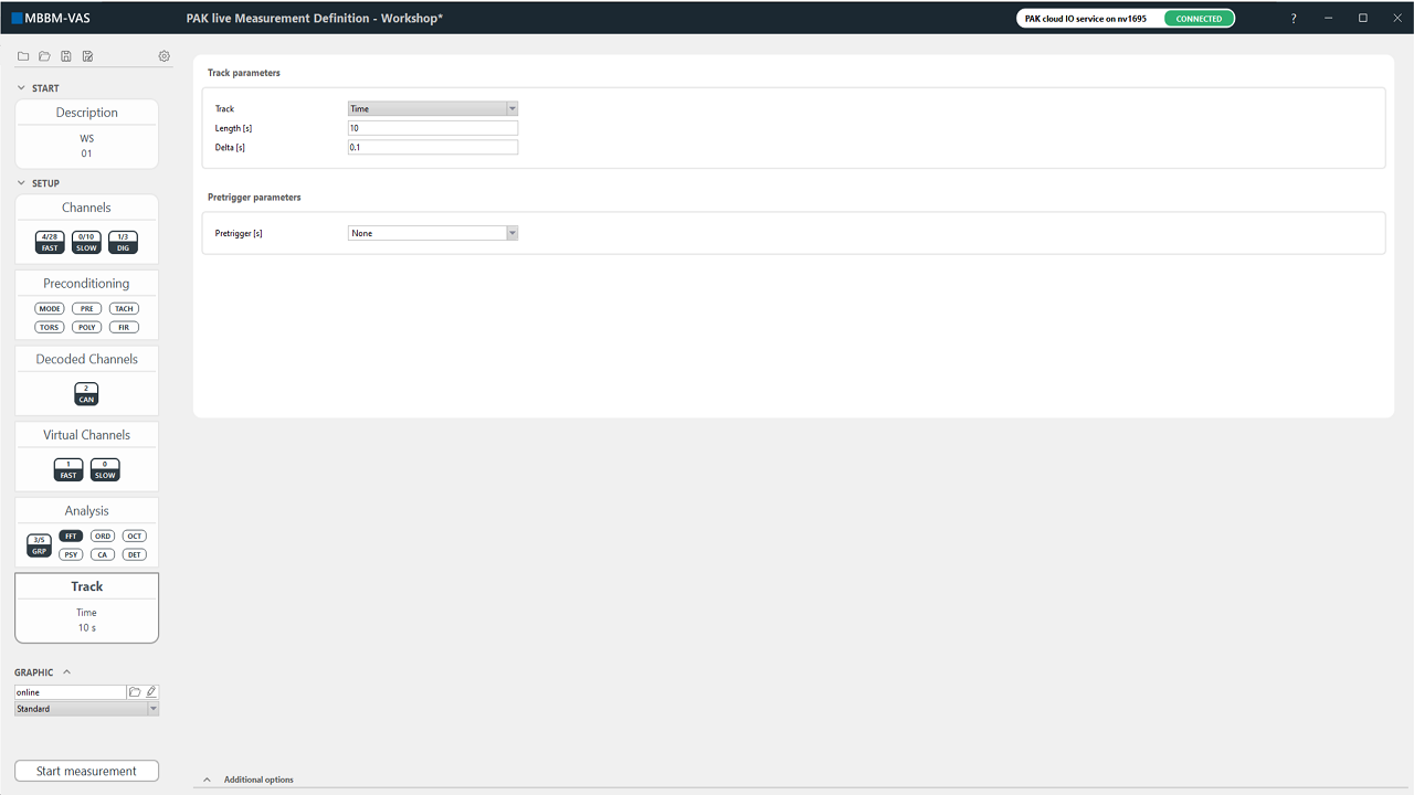
Last but not least, you need to define your track parameters on the "Track" navigation element. This behaves similar to the well-known classic PAK. Simply select your track of choice and adjust desired settings.
If wanted you can configure an online graphic definition. Below the navigation elements you find the part "GRAPHIC" with an pen-shaped icon next to it. Click the icon, enter a name and open the known grapic definition interface. Here you can configure channels for your online graphic definition just as you know it in classical PAK. The dropdown menu below the name entry shows your tabs of the created graphic definition.
You successfully configured and set up a measurement with the PAK live measurement definition. Click "Start measurement" to open your measurement interface.
Measurement Interface
The measurement interface looks almost the same as you would expect it from classic PAK. You have the online graphics, control panel, the slow quantities and the level indication. While most remained the same the level indication changed.
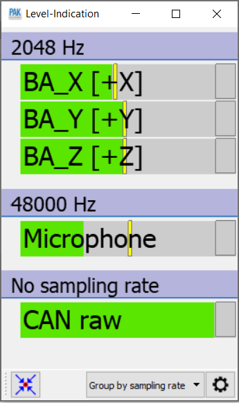
You can now sort your indication bars as predefined in the dropdown menu. Furthermore, you can configure the layout of the indication bars at the gear-shaped icon. Note, that virtual channels are not displayed at the level indication.
Since you are working with PAK live you are - depending on your track parameters - instantaneously able to perform measurements. There is no initialization necessary.
Loading a PAK live Measurement Definition
As mentioned above, with this PAK live measurement definition you are able to save and load your setups. However, this raises the demand for a proper workflow since all settings are applied directly on the connected devices. Therefore, if you are loading a previous PAK live measurement definition an internal comparing process collates the stored settings from your loaded file with the recent settings coming from the connected devices. If there is a mismatch you will be prompted to decide if you want to push your loaded settings to the device or pull the recent settings into your loaded setting.
Let us illustrate this case at this example here. In the process of setting up the measurement above I created and saved a PAK live measurement definition "Workshop" with the position label "BA_X", "BA_Y", "BA_Z" for the respective directions of the channels connected to the triax sensor. Let us now assume a colleague worked with the same devices but for a different use case and he renamed these three channels. If I want to work with my setup "Workshop" again I would just load it. But since the internal check recognizes a difference between the loaded settings and the recent settings on the device I need to decide how I want to proceed.
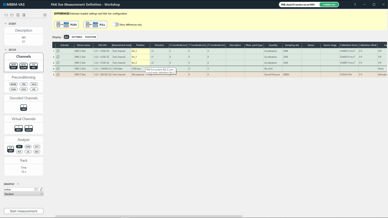
Before I can continue working I either push the local settings onto the device or pull the recent settings into my current setup. All differences are highlighted in yellow, additionally a tooltip will be displayed by hovering with the mouse over a yellow entry. It shows explicitly the difference for the selected entry.
In this case, I certainly would not want to pull the settings resulting into my current measurement definition. I would push my selected definition with all settings onto the devices and continue working.